Mechabot: Autonomous Mobile Robot (AMR)
Mechabot is a two-wheel differential-drive robot that I built in ROS 2 and Gazebo, one layer at a time: robot model, physics and controllers, teleoperation, sensors, an autonomous QR-code maze solver, SLAM mapping, AMCL localisation and Nav2 navigation. All of it runs in simulation, and one bringup launch file starts the full system.
I started with a plain URDF of a two-wheel robot and checked it with robot_state_publisher and the joint state GUI. Then I split it into xacro files (base, sensors, Gazebo, ros2_control) and added the Mechabot STL meshes. A launch file converts the xacro and opens RViz. The TF tree has base_footprint at the root, then base_link and the two wheel links.
Gazebo needs <inertial> and <collision> on every link, so I added them with primitive shapes, not meshes. The drive wheels have high friction and the castors have low friction, so the castors slide. The gz_ros2_control plugin connects Gazebo to the controller manager, which runs a joint state broadcaster and a diff_drive_controller with velocity command interfaces on both wheel joints.
twist_mux selects one velocity source by priority: joystick (99), Nav2 (90), keyboard (80). The joystick did not move the robot at first. ros2 topic info -v showed the cause: a relay node published Twist, but the controller in ROS 2 Jazzy expects TwistStamped. I removed the relay and set the whole chain to stamped messages: joy → joy_teleop → twist_mux → /wheel_controller/cmd_vel.
A 360° GPU LiDAR (360 rays, 0.15–12 m, 5 Hz, Gaussian noise), an IMU and an RGB camera, bridged from Gazebo to ROS 2 with ros_gz_bridge. The camera has an extra optical frame, because ROS uses X forward and OpenCV uses Z forward. The IMU is there to correct wheel-odometry drift. Three small scripts read each sensor: distances in four directions, yaw and yaw rate, and a live camera view.
I modelled a maze in Blender and made it a Gazebo model. Three QR-code markers on the walls say left, right and stop. I placed the models by dragging them in the Gazebo GUI and saved the world. A detection node reads the camera image with OpenCV, decodes the QR text and draws a box and a label on the frame.
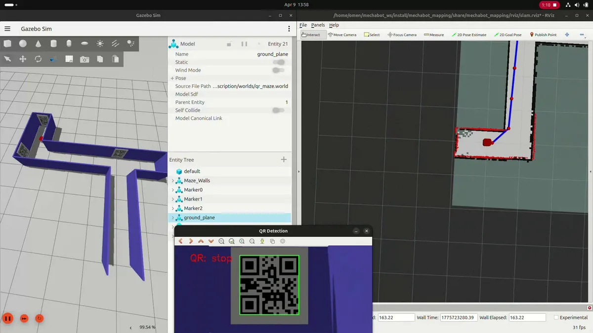
The solver node uses the camera, the LiDAR and the IMU, and runs a state machine every 0.1 s. In FORWARD, the robot drives until the wall in front is 0.45 m away (the average of the 40 front LiDAR rays, ±20°). Then it reads the QR code: left or right starts TURNING to the current yaw ±90°, until the error is below 0.1 rad. stop ends the run. Angle normalisation handles the wrap at ±π.
Odometry alone drifts because of wheel slip and encoder noise, so the robot needs a map. slam_toolbox uses the LiDAR and odometry to build a 2D occupancy grid while the robot drives. Nav2's lifecycle manager starts the nodes in the correct order. I saved the map with map_saver_cli and cleaned stray pixels in GIMP.
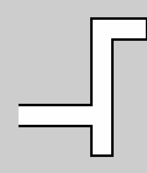
With a saved map, the robot only needs its pose. A new localisation package runs map_server and nav2_amcl (adaptive Monte Carlo localisation), which matches LiDAR scans to the map. One launch argument selects the map, for example the AWS small house world.
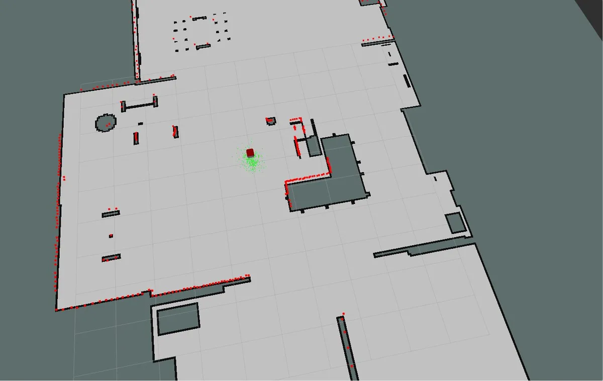
A behaviour tree plans a path to the goal again at 1 Hz and follows it. If it fails, it recovers up to three times: wait 3 s, back up 0.30 m at 0.15 m/s, then spin. A behaviour server provides the spin, back-up and wait actions.
What I learnt
- Debugging ROS 2:
ros2 topic info -v,ros2 control list_controllersandview_framesfind most problems fast. Most of my bugs were message-type mismatches. - Simulation details: collision shapes, inertia, friction and sim time (
use_sim_time) all change how the robot behaves. - Why each layer exists: odometry drifts, so SLAM builds a map; with a map, AMCL only finds the pose; Nav2 plans and recovers on top of that.
- Clean structure: one package per job (description, controller, scripts, mapping, localisation, navigation, bringup) keeps the system easy to change.